Skip to content

Blog Overview

Welcome to the Blog section. This page is the central place for curated posts and resources.

What to expect

  • clear, organized posts grouped under one blog path
  • a site structure that matches the MkDocs blog plugin
  • easy navigation via the Blog menu item

The Illusion of Autonomy in Modern AI Systems

The Problem: Everything Is Suddenly “Autonomous”

Today, every product pitch, conference keynote, and AI‑agent demo is saturated with the word “Autonomous.”
It has become a marketing slogan rather than a technical reality.

Before accepting the label, we need to pause and ask:

What do we actually mean when we call a system “autonomous”?


What Autonomous Really Means

Autonomous literally means self‑governed.
It comes from two Greek roots:

  • autos — self
  • nomos — law or rule

An autonomous system has the freedom and authority to govern itself, make its own decisions, and operate independently without external control.

This definition is powerful — and also unsettling.

Because a truly autonomous system would be:

  • defining its own rules
  • interpreting its own constraints
  • deciding its own actions
  • operating without waiting for human approval

This naturally triggers discomfort:

  • Do we want a system making its own decisions?
  • Acting independently?
  • Operating without human oversight?

Most people — and most industries — instinctively say no.


Controlled Autonomy

Controlled autonomy describes systems that appear autonomous but operate within strict, predefined boundaries.
Control and autonomy are inversely proportional — the more control we impose, the less autonomy the system actually has.

Controlled autonomy is typically implemented through:

  • hardcoded rules
  • rigid design‑time constraints
  • standard operating guidelines
  • whitelisted decision paths
  • deterministic workflows

The system cannot deviate from these structures.
It may look autonomous, but its behavior is tightly governed by external authorities — designers, operators, regulators.

In reality, this is automation, not autonomy.

This is why controlled autonomy is often called bounded autonomy — independence inside a cage.


Autonomy

Autonomy represents the opposite end of the spectrum: self‑governed operation.

An autonomous system:

  • establishes its own operating principles
  • adapts based on internal reasoning
  • learns from experience
  • responds to dynamic, real‑time situations
  • regulates itself without external enforcement

True autonomy requires:

  • Broad decision‑making freedom
  • Minimal hardcoded constraints
  • Contextual interpretation and adaptation
  • Internal rule formation and self‑regulation

No AI system today meets this definition.
Many are marketed as autonomous, but they operate under significant external constraints, safety rules, and human oversight.

Autonomy remains aspirational, not achieved.


Governed Autonomy

Governed autonomy sits between rigid controlled autonomy and full self‑governance.
It is the most realistic and responsible model for modern AI systems.

In governed autonomy, the system has broad operational freedom, but within a governance framework that ensures safety, alignment, and accountability.

Key characteristics include:

  • Just‑in‑time decision making based on real‑time context
  • Fewer hardcoded rules, enabling flexibility and adaptation
  • Runtime evaluation instead of design‑time scripting
  • High‑level governance principles rather than micromanagement
  • Dynamic policy enforcement instead of static rule enforcement

Governed autonomy allows systems to behave intelligently and responsively while ensuring that human‑defined values, constraints, and oversight remain intact.

It is autonomy with responsible boundaries, not autonomy with rigid restrictions.


Summary

Model Description Reality Today
Controlled Autonomy Independence within strict, predefined boundaries; essentially automation with limited decision freedom. Common and widely deployed.
Governed Autonomy Adaptive, context‑aware autonomy guided by governance principles rather than rigid rules. Emerging and most practical.
Full Autonomy Self‑governed behavior where the system defines and follows its own rules. Not yet ready with current AI.

WSL2 on Windows

Windows operating system provides "Windows Subsystem for Linux" which can be utilized to develop using Linux operating system and have Linux based tools. Windows operating system is providing a great interoperability so that it is very easy to operate between Linux distribution and base operating system. I still remember the old days where we had to do so many things to have Linux OS with the base operating system. Popular choices were to have dedicated partitions to have different Operating systems or have Virtual Machine to host any OS of your choice. For both the cases, the development experience was not that great.

Modern development is based on Containerization technologies and for Windows operating system, Docker Desktop is a popular choice to create docker environment in Windows operating system. Docker Desktop was using Hyper-v based virtualization technology and Linux OS to provide required environment. Later it started supporting WSL to provide containerization capabilities.

Recent licensing agreement says Docker Desktop is not free for enterprises and you need license to use it. Docker Desktop is a great tool but it has license cost associated with it. New tools are coming like Rancher Desktop which shows great potential. You may explore these tools if you are comfortable using GUI based tools. If you are comfortable using command and CLIs then you can setup you own environment using WSL2.

I have recently configured my development setup using WSL2 on Windows 11.

I have noted all the tips and tricks to resolve the issues which I encountered during this journey.

Step 1 : Setting up WSL 2 in WINDOWS 10/11

Go to Windows + R and enter appwiz.cpl

Click on "Turn Windows Features on or off" . Enable "Windows Sub System for Linux" and "Virtual Machine Platform" Then restart the machine.

Open power shell

wsl --install

If WSL is already installed

wsl --update 

Setting WSL2 as default

wsl --set-default-version 2

How to see available distributions?

wsl -l -o

How to check installed distributions

wsl -l -v

Installing specific distribution

wsl --install -d <distribution name>
# example : wsl --install -d Ubuntu-20.04

Note down username and password.

To Stop distribution :

wsl --terminate Ubuntu-20.04

To unregister distribution :

wsl --unregister Ubuntu-20.04

Step2 : Mounts - accessing windows file in Linux and vice versa

Find Linux packages under windows folder

C:\Users\<uername>\AppData\Local\Packages\CanonicalGroupLimited.Ubuntu20.04onWindows_79fggfdhp1fndgsc

Seeing Linux files in WINDOWS Locating distribution files in windows -

\\wsl$

This will show all the distributions and you can enter into specific distributions

\\wsl.localhost\Ubuntu-20.04

Accessing Windows file system in WLS distribution use /mnt to navigate any to drive.

Example :

cd /mnt/c
# or 
/mnt/d/<sub-folder>

use ls command to see the files

testuser@vvdsfsf04:/mnt/c$ sudo ls

To go back to root -

testuser@vvdsfsf04:/mnt/c$ cd ~

Step 3: Using Visual Studio Code to modify Linux projects

Installing and opening VS code form WSL distribution

testuser@vvdsfsf04:~$ code .

It should open Visual Studio Code with Linux terminal so that you can execute any Linux command from here. You can install "Remote WSL" extension upfront.

You can also connect WSL distributions form visual studio Open Visual Studio Code Press Ctrl + Shift + P and the search "new WSL window with Distribution". You should be able to select installed distributions.

Step 4: Windows terminal

It is better to use windows terminal to access all the Linux distributions. You can install from Windows store or any other procedure as mentioned in the below link Microsoft Terminal

Note:- Windows 11 it is pre installed.

Sometimes for corporate environment windows store is not available. in that case use Powershell and package manager -

winget install --id=Microsoft.WindowsTerminal -e

Windows terminal shall provide distribution specific terminals and it is easy to operate multiple distributions

Step 5 : Internet Connectivity inside WSL distribution

sudo apt-get update

If you see it is not working follow the below steps

Generally for personal computer you do not need to any thing but sometimes for corporate network you need to some configurations. This a hack which I did to get internet connections but we need to have a better solution. I will update this section once I have some update.

Step 5

Step 5.a : Create a WSL conf file under /etc/ folder

sudo nano /etc/wsl.conf

Paste the below text

[network]
generateResolvConf = false

Step 5.b : Remove default resolv.conf

sudo rm /etc/resolv.conf

Step 5.c : Create new Resolve.conf

sudo nano /etc/resolv.conf

and paste

nameserver 8.8.8.8

Now, Restart the distribution

Step 6 : Installing Docker

Docker installation and Docker Compose installation Use below commands to start docker immediately and start docker while starting up the OS.

sudo systemctl start docker
sudo systemctl enable docker
sudo systemctl enable docker.service
sudo systemctl enable containerd.service

If you see the below error --

System has not been booted with systemd as init system (PID 1). Can't operate. Failed to connect to bus: Host is down

You can use instead

sudo service docker start
sudo --status-all

Avoid starting every time, You can follow the below steps to start at start-up --

Step 1:

sudo visudo

ALL=(ALL) NOPASSWD: /usr/bin/dockerd

Step 2:

echo '# Start Docker daemon automatically when logging in if not running.' >> ~/.bashrc
echo 'RUNNING=`ps aux | grep dockerd | grep -v grep`' >> ~/.bashrc
echo 'if [ -z "$RUNNING" ]; then' >> ~/.bashrc
echo '    sudo dockerd > /dev/null 2>&1 &' >> ~/.bashrc
echo '    disown' >> ~/.bashrc
echo 'fi' >> ~/.bashrc

Step 3:

sudo usermod -a -G docker <<user>>

Step 7: Accessing Linux applications from WINDOWS

Microsoft Networking

ip addr | grep eth0

From Windows - https://172.20.80.183/

Step 8: Accessing Windows applications from Linux

cat /etc/resolv.conf

From Linux -- curl http://172.20.80.1:500

Internet Protocol Suite

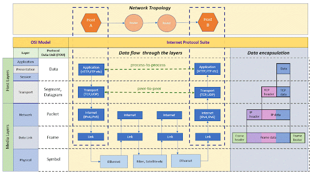
Internet Protocol Suite is the protocol stack used on internet. This is a conceptual model built based on a set of communication protocols used in internet. It is commonly known as TCP/IP because of two main protocols – TCP (Transmission Control Protocol) and IP (Internet Protocol). It consists of four conceptual layers –

  1. Application Layer
  2. Transport Layer
  3. Internet Layer
  4. Link Layer

These layers are not directly mapped to OSI communication model, rather it is loosely mapped to the seven layers of OSI communication model.
Architecture

Internet Protocol Suite

Above pictures explains how data flows through the layers and data encapsulation at each layer. it also shows a mapping of OSI communication model. However, if only represents a loosely mapped 7 layers of OSI communication model.

Link layer is a local network connection attached to a host. This consists of specialized hardware, virtual private networks (VPN) and network tunnels. Packets are transmitted and received via this link layer, moved by utilizing device drivers, firmware to transmit the frames to Physical layer.

Internet Protocol Layer

Internet protocol layer is used to send data packets (called datagrams) from source network to destination network. It can accommodate any transport layer protocol which can carry different data structures. This means, internet protocol layer is agnostic to both data structure and transport layer. It uses a routing technique to identify the path inside/across networks. Routing uses different type of delivery schemes and algorithms to determine the paths. Routing delivery schemes are –

  • Unicast – delivering messages to a specific node; one-to-one
  • Broadcast - delivering messages to all the nodes; one-to-all
  • Multicast – delivering messages to a specific group of nodes; one-to-many-of-many or many-to-many-of-many
  • AnyCast – delivering messages to a specific node of a group of nodes; one-to-one-of-many
  • Geocast – delivering messages to a group of nodes available in a specific Geographic location; one-to-many-of-many-at-geolocation

It uses Internet Protocol Version 4 which is a 32-bit address. Now, in today’s world of Internet of Things IPv4 is not sufficient to accommodate all IPs. To overcome this Internet Protocol Version 6 which uses 128-bit addresses.

Transport Layer

Transport Layer enables peer-to-peer communication between hosts. This acts as a data channel and this is independent of the data structure defined by the users. It supports two modes of communications 1. Connection oriented and 2. Connection less. Transmission Control Protocol (TCP) is the implementation of connection oriented and User Datagram Protocol (UDP) is for connection less. It maps to the 4th layer of OSI Communication model.

Application Layer

Application Layer uses different type of protocols to exchange data between applications. This layer provides required abstraction for the transport and lower layers. Some of the popular protocols are Hypertext Transfer Protocol (HTTP), File Transfer Protocol (FTP), Web Socket, Simple Mail Transfer Protocol (SMTP). It combines top three layers (Application, Presentation and Session) of OSI communication model.

How internet has evolved overtime?

It’s amazing to see how the contribution from different research put together created Internet which made a great impact to the society. It is worth knowing on all the contributors and the concepts which is still valid for modern architecture.

In 18th century, the study of electromagnetism had given opportunity to build long distance communication systems. Two significant research focus were Electric Telegraphy and Wireless Telegraphy. I will keep the focus on Electric Telegraphy and Telephony to explain the history of internet.

An effective long-distance communication was started with Electric Telegraph. The core concept was transmitting electric signals over a wire. It all started with Battery(cell) invention in 1800 by an Italian physicist Alessandro Volta (1745-1827). In 1820, Danish physicist Hans Christian Oersted (1777-1851) identified a connection between electricity and magnetism. The demonstration could deflect a magnetic needle using electricity. Researchers across the world were working on a communication system based on the principle of electromagnetism. Electric telegraph was invented separately by two sets of researchers: Sir William Cooke (1806-79) and Sir Charles Wheatstone (1802-75) in England, and Samuel Morse (1791-1872), Leonard Gale (1800-83) and Alfred Vail (1807-59) in the U.S. In 1830s British researchers (Cooke and Wheatstone) developed a telegraph system in which a magnetic needle could point to a letter or number printed in a panel. In 1832, Morse developed an electric telegraph which was based on dots and dashes. Later, he had a partnership with Alfred Vail and together they made lot of improvements in Morse system. They created a single-circuit telegraph that worked by pushing the operator key down to complete the electric circuit. This requires sending an electrical signal over the wire and a receiver at another end. In 1843, they got funding from U.S. government to setup a telegraph system. A wired connection was made from Washington, D.C., and Baltimore, Maryland. On May 24, 1844, a historic day; a first message transmitted: “What hath God wrought!". This started a new era of electric Telegraph. They also developed a code called Morse code for effective transmission of messages. Each letter was having a unique code and when code is reached at other end; it makes a mark in a piece of paper and later translate back in English. Later operators were able to understand the code by listening the clicks at receiver end.

This telegraph era was survived for next 100 years and series of innovation and initiatives were made. Few major events are listed below -

  • In 1856, Western Union Telegraph Company was formed
  • In 1865, International Telegraph Union was formed
  • In 1871, transmission improvement happened where first duplex system is introduced where same line can be used for both sending and receiving communication.
  • In 1871, Jean-Maurice-Émile Baudot introduced a concept called multiplexing (switching). In this system, correct transmitter and receiver had to be connected.
  • In 1872, Western Electrical Manufacturing company was formed (It was initially an electrical company started under the name of Gray and Barton in 1869).
  • In 1874, Thomas Alva Edison introduced a quadraplex telegraph system where 4 messages were transmitted simultaneously in a single line.
  • In 1876, Alexander Graham Bell invented Telephone.
  • In 1877, Bell Telephone Company and a sister company “New England Telephone and Telegraph Company” were formed. Later in 1879, merger happened and two new entities were formed - National Bell Telephone Company of Boston, and the International Bell Telephone Company
  • In 1880, American Bell Telephone Company was formed. Merger between National Bell Telephone Company and American Speaking Telephone Company.
  • In 1882, American Bell Telephone Company acquired Western Electrical Manufacturing company.

Until 1950, communication was all about telegraph, telephone network and broad cast radio (wireless). On 4th October 1957, Soviet Union successfully launched Sputnik which was the world’s first artificial satellite. In response to this event, U.S. defense launched an advanced research program. The internet we are seeing today, was started with a defense/military initiative. As it says, “Necessity is the mother of all invention”, probably the ambition to conquer the world and create a footprint; gave us technology that no one could imagine at that time.

On 7th-February-1958, Advanced Research Projects Agency (ARPA) was formed, later it was renamed to Defense Advanced Research Projects Agency (DARPA).

Main 2 core concepts were very popular at that time – Time Sharing and Packet Switching.

Time Sharing – An interesting concept was getting developed where a computer can be used simultaneously by multiple users. The whole idea was to handle multiple problems concurrently. Lot of researchers contributed to this idea. The first idea proposal was done by John Backus in the 1954, followed by many new developments in late 1950s and early 1960s.

Packet Switching – A significant contributions were made by 3 research organizations –

  • RAND Corporation (Military Network)
  • National Physical Laboratory – NPL (Commercial Network)
  • CYCLADES (Scientific Network)

In 1960s Donald Davis (UK) from NPL gave the first idea on “Packets”. In his proposal, data were split into multiple packets and assembled back at receiver end. Also, Paul Baran from RAND Corporation, proposed similar idea. Baran proposed dividing data into “message blocks” before sending them across network and rejoin them after collecting at the receiver end. Packet switching is a store and forward mechanism. In a network there were Switch points called switch (also called router) which examines the packet’s destination address and forwards the messages in an appropriate line. In 1965, Donald Davis proposed another paper on packet switching which envisioned to transfer computer data over routers. Other side at RAND Corporation, Paul Baran continued his research on distributed computing and decentralized architecture of networks. He also proposed digital packet switching over analog system. Many papers were published on distributed communication. He proposed a distributed communication where data can still be transmitted even if few nodes(routers) are damaged. He proposed a scheme called “hot-potato-routing” to transmit messages.

Other developments were also happening in parallel. In 1961, Len Kleinrock from MIT, published a paper called “Information flow in large communication nets”. In 1962, another and most important idea came out from MIT professors J. Licklider and W. Clark called “Man computer communication” where they envisioned users to use terminals to use large computers. Licklider proposed another concept called “Galactic Network”.

In 1966, L. Roberts (DARPA) proposed a computer network called ARPANET to share information. This initiative gave us the foundation for Internet.

In 1967, ARPANET gave a contract to Bolt Beranek and Newman (BBN) to build Interface Message Protocol (IMP) which would implement packet switching over nodes. Main idea was to connect computers over telephone network. BBN created first piece of IMP hardware which can be attached to the computer.

In 1969, it was planned to send first message “LOGIN”. The setup was established between USCLA and STANFORD. This setup was able to send L and O but system crashed when it tried transmitting G…. There is nothing called failure in scientific research and on that day, the world got something to take it forward.

Later the network got expanded across U.S. The first ever routing protocol which was used in ARPANET was “distance vector routing”.

In 1971, a program called CPYNET used ARPANET to send files to remote computers. Ray Tomlinson introduced a concept called EMAIL by introducing @ symbol which attach a host name to the message.

In 1972, France delegates created another network called CYCLADES (inspired by ARPANET). It introduced interesting concepts like “datagrams” where network host was responsible for data than the network itself. This had huge influence in designing TCP/IP protocol. It also worked on many interesting concepts like sliding window protocol, Layered architecture for networks.

In 1972, the idea of open architecture was first proposed by Bob Khan. He introduced a protocol called Network Control Protocol (NCP). NCP did not have the ability to address individual machines other than a destination to IMP. In between 1973-75, Vint Cerf and Bob Khan together created TCP (Transmission Control Protocol) and IP (Internet Protocol). TCP used sliding window protocol.

Now, the requirement on standardization was very prominent as there were various networks with different types of packet switching implementations. This was having an interoperability issue. Khan’s rules of interconnection were recommended –

  • Each network is independent and must not be required to change
  • Best-effort communication
  • Boxes/Gateways connect networks
  • No global control at operations level

Initial proposal came for 8 bit network identification which could cover 256 addresses.

In 1973, ARPANET was extended to trans-Atlantic connection where Email was the popular application.

In 1975, first email client was created by John Vittal (University of Southern California)

In 1977, PC modem was developed by Dennis Hayes and Dale Heatherington.

In 1978, a concept of layering came into the picture. TCP and IP were separated; TCP is used at the endpoints and IP in the networks. Then ISO (International Standardization Organization) was created. They came up with a 7-layer OSI reference model.

In 1979, IP version 4 was documented.

From 1979 to 1982 many applications are created like Usenet, ENQUIRE software, emotion. First emotion was “:-)”

In 1982-83, U.S. defense standardized on TCP/IP stack. ARPANET installed TCP/IP stack in production. Berkeley’s computer created Unix based machines with TCP/IP stack and sockets.

In 1984, DNS (Domain Name Service) was introduced.

In 1985, National Science Foundation (NSF) selected TCP/IP as the standard internet backbone to connect all the networks together.

In 1989, AOL was launched.

In 1989, Tim Berners-Lee proposed World Wide Web (WWW). It was initially called “Mesh”

In 1990, ARPANET was shut down.

This was a new beginning……today we can see how internet has become the part and parcel of our daily lives!

References-

  • https://www.history.com/topics/inventions/telegraph
  • https://www.britannica.com/topic/Western-Electric-Company-Inc
  • https://www.britannica.com/technology/telegraph
  • https://www.youtube.com/watch?v=oIezCGjxV3A
  • https://www.youtube.com/watch?v=RN4gSBTANUY
  • https://en.wikipedia.org/wiki/Bell_Telephone_Company
  • https://www.britannica.com/topic/Defense-Advanced-Research-Projects-Agency
  • https://www.webfx.com/blog/web-design/the-history-of-the-internet-in-a-nutshell/
  • https://www.communicationsmuseum.org.uk/emuseum/packetswitching/
  • http://student.ing-steen.se/IPv4/TCP-IP.pdf

Digital Twin & Actor Model

Digital Twin Actor Model

Digital Twin is a digital representation of physical objects like device, process or system. In IoT world, digital twin can help us monitoring entire life cycle of devices. AI and Machine Learning modules can be integrated with digital simulation. Digital twin needs to be updated frequently so that it maintains same copy of physical object’s properties and state. 3D modeling and Augmented reality can be used to enable visualization with respect to creation and monitoring of Digital Twins.

In this topic, let us see how Digital Twin, Actor Pattern and Azure Fabric can be useful.

In today’s world, Micro service based architecture has decent impact on business. Businesses needs to be true agile on whatever they are doing — it could be Development, Efficient/Faster deployment, Effective maintenance and so on…Traditional architectures are good on separation of layers but they are very difficult to scale and maintain. To meet the above needs, micro service based architecture splits entire systems into small and independent services.

Stateless services need to maintain state in a separate persistence store. In the Modern computing world, it is always better to keep the compute and store together. Stateful services are useful in this context.

Azure service fabric is a micro services platform to build scalable and reliable micro services. This is a PaaS offering from Microsoft. It supports container based apps, Stateless service, Stateful service and Actor service. For more information refer Azure Service Fabric

Actors and Digital Twin and IoT

Actors are independent single unit of state and logic. It is based on Actor Pattern. Actors are computational units deployed with a large number and executes simultaneously and independently of each other. They can communicate with each other and also can create more actors.

In Microsoft world, it is called Service Fabric Reliable Actors which is an implementation on actor design pattern. Refer Microsoft documentation on Reliable Actor.

Internet of things (IoT) is where huge number of things are connected. Apart from the security and management of things/devices, it is also important to have a digital representation of them. This virtual model of devices exist in the Cloud and it has both state and logic. The model can be updated with the telemetry data produced by the device or sensors. This can be an enabler towards Digital Twin where we can have virtual model of process, product or service.

Following are few use cases that can be addressed –

  • Can have Digital Twin as simulated objects and push the changes to virtual model and observe the effects
  • Monitoring and diagnostics of physical objects using Digital Twin
  • Combination of digital twin and 3D modeling enables better visualization for both creation and - monitoring of physical devices
  • Artificial Intelligence and Machine Learning modules can be integrated with Digital Twin.

Architecture – Service Fabric Actor and IoT

Actor Model IoT Architecture

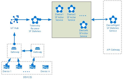
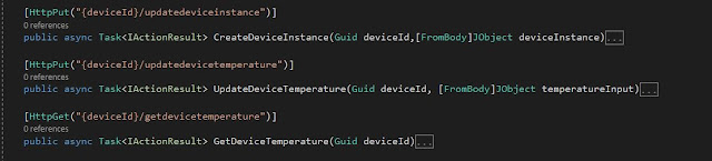
This is a simple architecture to show the basic capabilities of Actor service to enable a basic digital twin. Let us see how to create and publish a digital twin using REST based API service and update the same with continuous telemetry. Also, we will see how to implement REST based API to GET updated property values.

We can create virtual model of Devices inside Service Fabric Cluster. It can be huge in number depending on the deployment on IoT solution. These Device Actors type contains information related to the actual device instance. Each actor instance has unique Id to identify. We can publish our device meta data and maintain other computational aspect of that device Type.

Just for this scenario I am trying to explain Actor model using IoT but remember actor model can be used on various other scenarios. In the above picture, API Gateway enables interaction with Digital twin which has all the relevant operations related to device – one of them could be creating device instance in service fabric cluster.

Actor Model IoT API

Physical devices are connected to IoT hub which is nothing but a cloud gateway where devices can be connected and managed securely. Once devices are connected to IoT Hub and the telemetry payload is uploaded to the cloud, Telemetry receiver (could be stateless or stateful) receives messages and identifies the right device actor to be updated. To resolve correct actor, payload should have right identifier or some mapping identifier. Also, REST based API can be used to update properties.

For Sample code refer GitHub repository.

Conclusion

As explained before these actors are single threaded and it will be available in the memory. No separate persistence is needed and an actor will have both state and logic. At any point of time, Business operations can have the latest snapshot of the devices. It also can have aggregation of values or some KPI based logic. It supports timers, reminders and sending notifications. Send notification feature is helpful to publish events to a client. This technology has good capabilities to create and maintain digital twins for both cloud and on-premise.